Solar Motor Kit
Project Summary
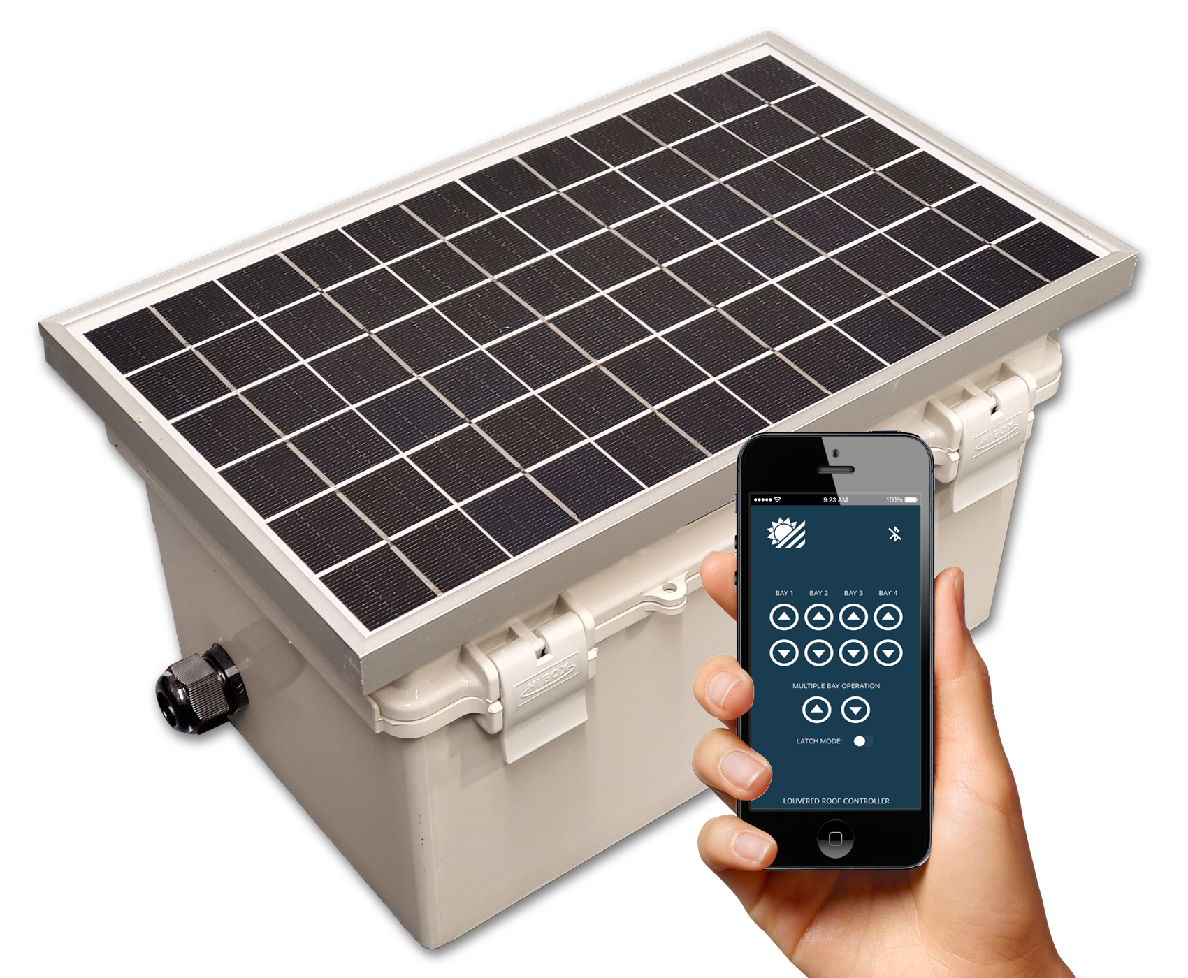
The Solar Motor Kit is a 12 volt DC motor driver system that is used to drive up to four linear actuator motors with a radio remote and Bluetooth smartphone app. It has a mounted solar panel that charges the internal lithium iron phosphate battery that comes within a weatherproof box.
My Development Process
The Solar Motor Kit is a solar powered motor driver system that is used to drive 12V linear actuator motors. Its mainly used for commercial outdoor patio projects where the roof system can have its panels opened or closed wirelessly. This Solar Kit is meant to act as the driving system that controls the motors to open/close the panels of the roof through the use of a wireless RF remote or custom Bluetooth smartphone application. I had to design and create this product that met certain goals while taking into consideration the project constraints.
Material Selection
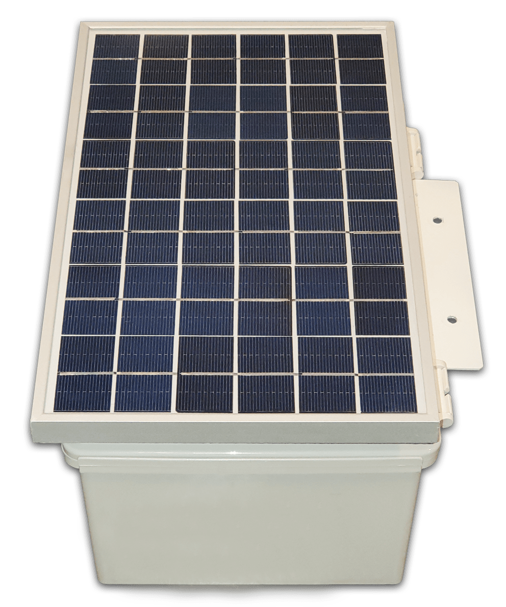
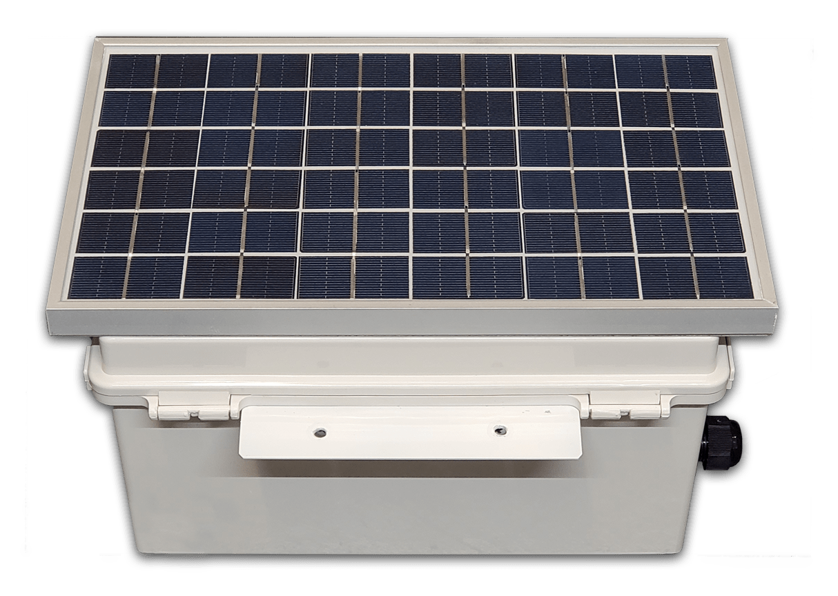
Not only did the product have to be solar, but the entire kit had to come as a complete unit. This means that the solar panel could not have been placed separately from the waterproof box. Therefore, a solar panel was chosen that would give enough power to the battery during the day while being able to be fastened to the top of the enclosure. During this phase, I accomplished the following:
- Researched different components for the solar circuit and tested them using a multimeter to assure that the system is self-sustaining.
Took into consideration the installers of the kit during the design to create an easy setup on the kit in the field.
Bluetooth Circuit Prototype
In order to give the solar kit a competitive edge in the market, a Bluetooth smartphone app was required to control the kit in addition to the RF remote that comes with the motor controller. During the prototyping process of this circuit, I accomplished the following:
Developed an Arduino microcontroller breadboard circuit that was able to accept commands from a dual-mode Bluetooth module, interpret them, and activate certain outputs depending on the command received.
Measured the overall power consumption of the prototype breadboard circuit to see if it is able to live off the battery without draining it entirely.
Modified the dual mode Bluetooth module via AT commands to change the Bluetooth names to be recognizable from the client side.
Bluetooth Circuit Board Design
Once the Bluetooth microcontroller circuit had been finalized, I had to design the printed circuit board to implement it onto the product. The circuit board was designed to work with a currently existing motor controller designed by a different manufacturer. My accomplishments during this phase of the project were the following:
Designed a circuit board that met the size constraint of the project. The final board was small enough to be fastened directly onto the motor controller which allowed for a neat setup.
The circuit board contained components that allowed the Bluetooth circuit to run off the battery while stepping down voltages to power each component safely.
Screenshots of Smartphone Controller App


